
 Subrex nozzles are engineered to dispense a measured amount of fluid onto a work-piece in a precise manner. The last point of interaction by a system, with a fluid, before discharge, is a nozzle. It is the component that engineers at Subrex have focused their attention on.
Nozzles, needles or tips as they are known and commonly referred to in the industry are designed to straighten, constrict and direct fluid flow to discrete locations on a work-piece. This aspect of a fluid delivery system is often the most overlooked and can be the difference between success and failure of a robotic or automated process to dispense fluids accurately, with reduced variability, to achieve high productivity.
Components are specifically designed and manufactured to optimize system performance so that impact upstream is minimized. Upstream conditions are dictated by the required flow-rate through the exit aperture of the nozzle, viscosity of the liquid and the pressure required to overcome resistance of a liquid to flow. Flow can be influenced through manipulation of viscosity. Viscosity can be altered by introducing shear force in some fluids or by the addition or removal of thermal energy from a fluid.
Design details of the body of a nozzle, needle, or tip and exit aperture can have a substantial impact on resistance to flow. More pressure is required to achieve the desired flow-rate when the output exhibits high resistance to flow from abrupt transitions between sections and restrictive aperture sizes that are required for a desired deposit placement. High-pressure requirements force the main upstream system component, the pump, to do more work to achieve the pressure necessary for fluid movement. The result is decreased accuracy and increased variation in the deposit volume. A correctly designed nozzle should not impede flow to the extent that an unnecessarily large pressure delta is caused by fluid flow through a nozzle.
Subrex products are based on engineering practices derived from extensive simulation and empirical testing.
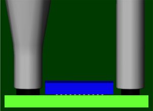
Nozzle offset distance comparison
This illustration simulates relative distance from a chip that exists in the fluid deposit between a conventional needle and a nozzle with a thinner wall. Thickness of the nozzle wall varies with exit aperture dimension and ranges from about 0.004 inch on larger sizes to less than 0.002 inch for smaller sizes. Subrex nozzles are produced to a run-out tolerance of less than 0.002 inch to further enhance placement precision of a fluid deposit.
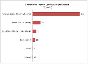
Relative Thermal Performance Comparison of Component Construction Materials
The chart shows approximate thermal performance between various materials used in construction of nozzles and needles relative to each other. Subrex nozzles are constructed primarily from copper alloys and can efficiently transfer heat into or out of a fluid to manipulate the viscosity of a fluid. Some applications require heat to reduce viscosity, others can benefit from removal of heat to increase viscosity. Manipulation of temperature can be a useful tool for process optimization.
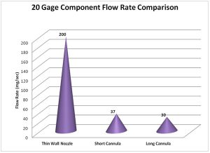
Flow comparison nozzle to cannula
The graphic representation above illustrates a superior advantage in flow rate a nozzle with a thin wall has in comparison to competitive nozzle designs. Short and long cannulae are ¼ inch and ½ inch, respectively. Comparison was made using the same fluid with equivalent pressure and time. Effective flow rate difference is dramatic between components.
Advantage increases as a thinner wall nozzle exit aperture size decreases. A nozzle with a thin wall demonstrates a significant performance improvement as wall thickness becomes a sizable percentage of the total projected area in smaller nozzles.
Wall thickness also varies along nozzle length as a function of internal diameter. Cross sectional area that results is sized such that pressure acting against a wall at a specific diameter results in minimum deflection. This enables the largest aperture possible while minimizing deflection at a given pressure.
Traditional medical gage tubing is based on a standard that is a function of an outside diameter dimension. Standard gage precision nozzles comply with this standard. A larger inside diameter for an equivalent outside diameter, generous transitions between sections, smooth walls and monolithic design all work in concert to maximize performance.
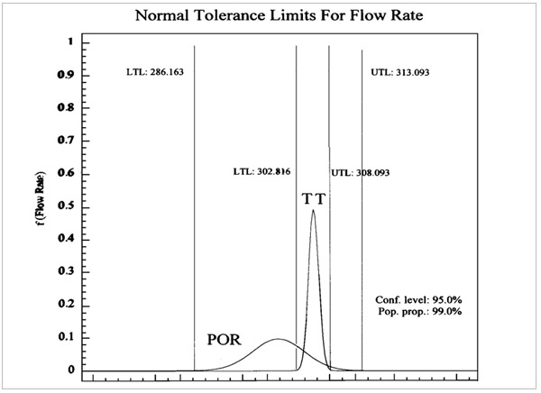
A standard gage precision nozzle (TT) in comparison to machined cannula style needle (POR)
This graph shows the dramatic reduction in flow rate variance that occurs on a positive displacement pump when standard gage precision nozzles are used. Each component is equivalent in size, they are both 20 gage. POR is a short ¼ inch, machined cannula style needle. Difference in width of the two curves illustrates the disparity by the distance between the tolerance limits for 99% of the population, with 95% confidence. Reduction in flow rate variance is approximately 510% or over five times less in comparison to the POR. This demonstrates the superior repeatability of a Subrex standard gage precision nozzle at achieving the desired flow rate. Significant reduction in backpressure reduces deflection of fluid path components and work energy requirements. Target flow rate is realized more rapidly due to reduced resistance to flow in the path. Fluid deposits are more precise when dispense time is short.
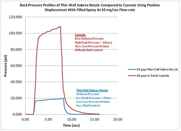
Back pressure comparison standard gage precision 19 gage nozzle and 18 gage machined ¼ inch long cannula.
Pressure measured at 65 mg/s flow rate for high filler content under-fill epoxy. Cannula peak pressure delta is more than 80% greater in comparison to a standard gage precision nozzle at the same flow rate.
Start and stop of deposit is crisp with a standard gage precision nozzle. Pressure is almost vertical rising and almost vertical falling to 10 psi with only slight curvature past that point as pressure returns to zero for a Subrex standard gage precision nozzle. Pressure remains relatively constant once steady state flow is achieved.
Cannula style needle pressure rise continues to increase although at a less dramatic slope for the entire duration of the dispense time. Pressure never comes close to reaching a steady state response.
Subrex standard gage precision nozzle pressure profile represents a low peak pressure combined with rapid rise and fall from transient to steady state pressure. This reduction in amplitude of the pressure pulse for thin and viscous fluids is a desirable attribute to have in a nozzle. The rapid decay of pressure in response to termination of flow in a standard gage precision nozzle reduces unwanted bolus volume.
Cannula pressure profile continues to decay for a substantially longer period of time after flow termination, pushing out additional unwanted bolus volume onto the work-piece. Drastic measures are necessary upstream to compensate for a cannula, to alleviate undesirable affects.